What Are the Most Common Design Mistakes in Photo Etched Metal Parts?
Photo etched metal parts are widely used in precision metal mesh, shims, electronic components, shielding parts, speaker grilles, filters, springs, nameplates, and mechanical structures. The process is ideal for thin, complex, burr-free metal components because it uses photochemical machining instead of mechanical cutting force.
However, successful photo etching depends heavily on design quality. A part may look correct in CAD but still be difficult, expensive, or unstable to manufacture if the drawing does not follow basic etching design rules. Below are the most common design mistakes engineers should avoid when developing custom photo etched metal parts.
1. Choosing Material Thickness Without Considering Etching Limits
One of the most common mistakes is selecting material thickness based only on strength or assembly needs. In photo etching, thickness directly affects minimum hole size, slot width, bridge width, tolerance, and edge profile.
Thicker metal usually requires larger openings and wider metal webs. Very fine details are easier to produce in thinner sheets. As a practical starting point, the minimum hole diameter, slot width, and bridge width should usually be close to or larger than the material thickness.
Before finalizing the drawing, engineers should confirm whether the selected thickness supports the required fine features.
2. Designing Holes and Slots That Are Too Small
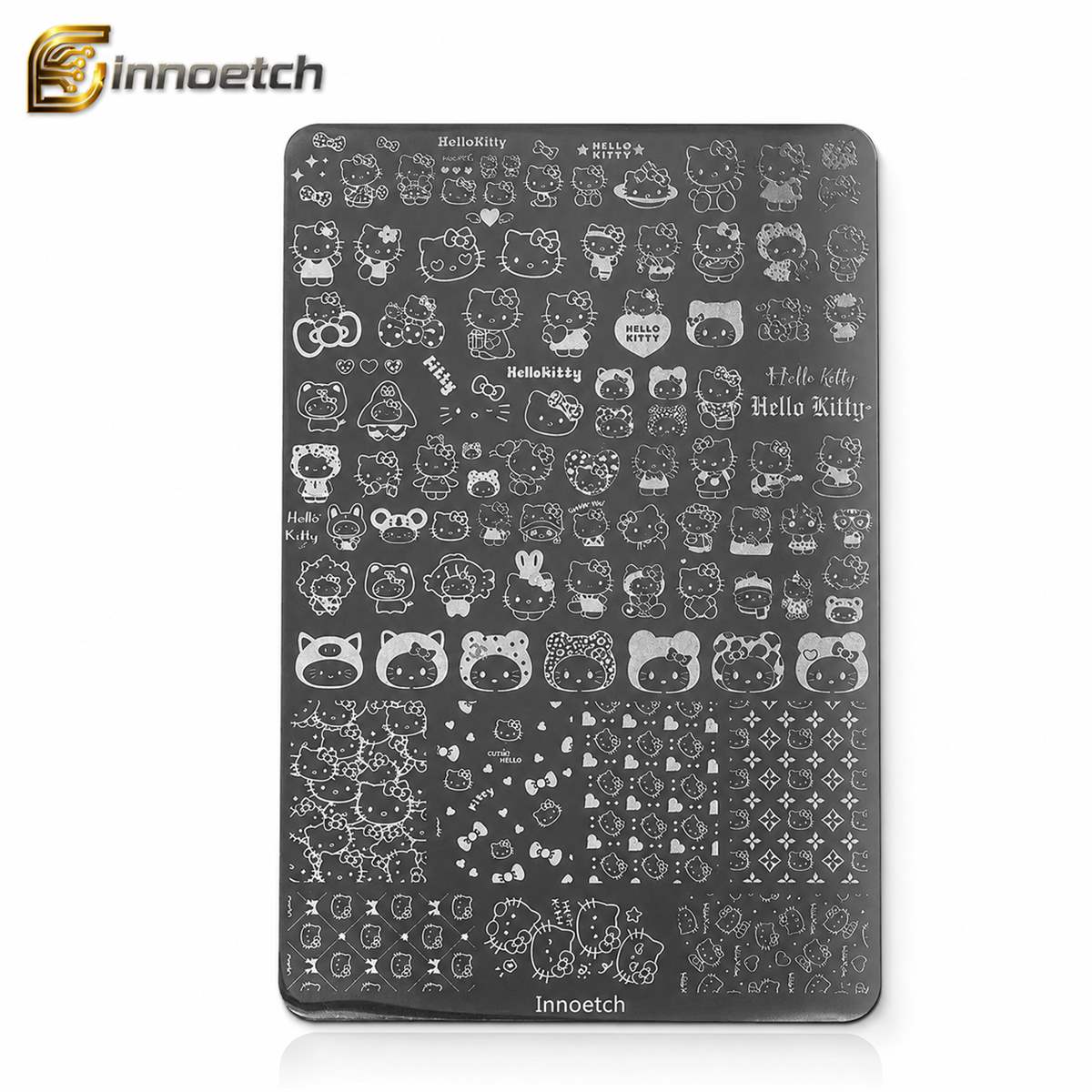
Small holes and narrow slots are common in etched filters, speaker grilles, ventilation parts, shielding components, and precision mesh. The mistake is assuming that any CAD geometry can be etched exactly as drawn.
If holes are too small compared with material thickness, they may become undersized, inconsistent, or difficult to open fully. Long narrow slots can also become unstable if their width is too small.
Better design practices include using realistic minimum openings, adding rounded slot ends, avoiding unnecessary ultra-fine features, and marking critical holes clearly on the drawing.
3. Making Bridge Widths Too Weak
Bridge width refers to the metal left between holes, slots, or cutouts. If the bridge is too narrow, the part may deform during etching, cleaning, handling, packaging, or assembly.
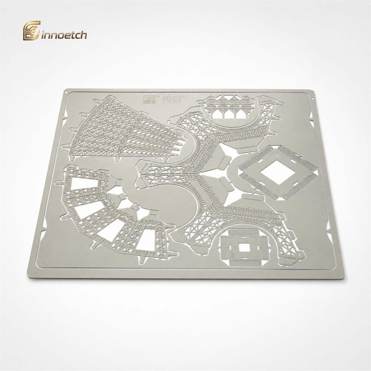
This mistake is especially common in high-density mesh, decorative patterns, speaker grilles, and lightweight structures. Even if a narrow bridge can be etched, it may not be strong enough for real-world use.
A good design should balance open area, airflow, filtration, appearance, and mechanical strength.
4. Applying Unrealistic Tolerances to Every Dimension
Photo etching can achieve high precision, but not every feature needs the tightest possible tolerance. Applying strict tolerances across the entire drawing can increase cost and slow production without improving part performance.
Engineers should separate dimensions into critical, functional, reference, and non-critical dimensions. For example, a spring contact, assembly slot, optical aperture, or filter opening may require tighter control than an outside decorative edge.
A clear tolerance strategy helps the manufacturer focus inspection and process control where it truly matters.
5. Forgetting to Define Critical-to-Function Features
Another common mistake is submitting a drawing where all features appear equally important. Manufacturers need to know which dimensions control performance, fit, conductivity, airflow, shielding, filtration, or assembly.
Critical features should be marked clearly. This may include hole diameter, mesh pitch, bend line location, contact area, slot width, open area ratio, or final formed dimensions.
When critical areas are not identified, engineering review becomes slower and production risk increases.
6. Using Sharp Internal Corners Without Radius Control
Perfectly sharp internal corners are difficult to achieve in chemical etching because the process naturally creates a small radius. Designing square internal corners, narrow V-notches, or sharp slot ends can lead to inconsistent results.
Engineers should use internal radii wherever possible. Rounded corners improve etching stability, reduce stress concentration, and make the part stronger during handling and use.
For slots, rounded ends are usually more stable than square ends.
7. Not Specifying Half-Etched Features Clearly
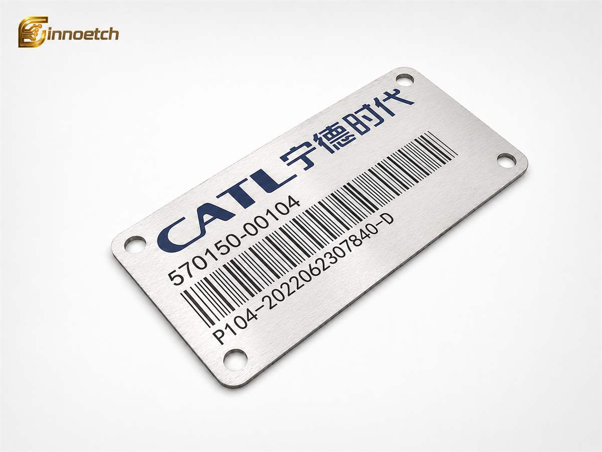
Half-etching is useful for bend lines, logos, part numbers, grooves, channels, recessed areas, and decorative textures. But half-etched areas must be clearly defined in the drawing.
Common mistakes include marking half-etching only by color, failing to specify front side or back side, omitting depth requirements, or not explaining whether the feature is cosmetic or functional.
A good drawing should specify the half-etch side, depth or remaining thickness, and intended purpose.
8. Placing Holes Too Close to Bend Lines
Photo etched parts can include bending and forming, but holes and fine features placed too close to bend lines may distort, crack, or lose dimensional accuracy after forming.
For bendable parts such as shields, clips, springs, brackets, and contacts, engineers should define the flat pattern and final formed shape. The drawing should include bend direction, bend angle, bend radius, and critical dimensions after forming.
If spring performance is required, material temper and heat treatment should also be reviewed early.
9. Submitting Incomplete or Unclean CAD Files
Poor CAD files are a major cause of quotation and production delays. Common file problems include open contours, duplicate lines, overlapping geometry, raster images instead of vector data, mixed units, missing scale, and unclear layer definitions.
For precision metal etching, clean 2D vector files are usually preferred. Useful formats include DXF, DWG, STEP, AI, vector PDF, and fully dimensioned PDF drawings.
The drawing should include material grade, thickness, tolerance, quantity, revision number, surface finish, and post-processing requirements.
10. Ignoring Surface Finish and Post-Processing Requirements
Some photo etched parts are purely functional, while others require decorative, conductive, corrosion-resistant, or clean surfaces. A common mistake is not specifying finish requirements until after sampling.
Surface and post-processing requirements may include passivation, plating, polishing, cleaning, heat treatment, forming, or protective packaging.
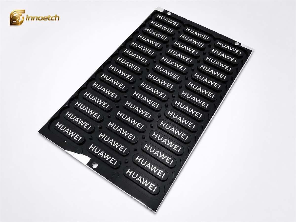
If the part is used as a contact, shield, filter, nameplate, speaker grille, or visible decorative component, cosmetic and functional surfaces should be clearly marked.
11. Designing Only for Etching, Not for Handling and Assembly
A part may be technically possible to etch but still difficult to handle, package, or assemble. Very thin frames, fragile tabs, narrow bridges, and unsupported details may bend or break after production.
Good design considers the entire product lifecycle: etching, cleaning, inspection, packaging, transport, assembly, and final use.
This is especially important for thin metal mesh, precision shims, elastic components, and electronic parts.
12. Waiting Too Long to Request DFM Review
Design-for-manufacturing review should happen before tooling and sampling. If engineers wait until the drawing is fully locked, small issues may become expensive to correct.
Early review helps confirm material choice, minimum feature size, tolerances, half-etching, bend design, open area ratio, and inspection method.
INNOETCH provides custom precision metal etching support from prototype development to mass production, helping customers improve manufacturability, consistency, and production efficiency.
Conclusion
The most common design mistakes in photo etched metal parts are usually preventable. Engineers should pay close attention to material thickness, minimum openings, bridge width, tolerances, corner radii, half-etched details, bend features, CAD file quality, and post-processing requirements.
By designing with the photo etching process in mind and involving an experienced precision metal etching manufacturer early, companies can reduce development delays, improve part quality, and achieve stable production for custom etched metal components.


Related Articles
How Can Dimensional Accuracy Be Improved in Custom Etched Metal Parts?
Explains how to improve etched part accuracy through clear drawings, material control, compensation design, inspection, ...
Jun 13, 2026How Does the Photo Etching Process Work from Prototype to Mass Production?
Outlines the photo etching workflow from CAD review and tooling to sample validation, process control, and mass producti...
Jun 13, 2026Why Is Photo Etching Suitable for Prototype Metal Parts?
Shows why photo etching supports metal prototypes through low tooling cost, fast design changes, fine features, and scal...
Jun 13, 2026When Is Chemical Etching Better for Thin Metal Parts Manufacturing?
Explains when chemical etching is best for thin metal parts with complex shapes, fine holes, low stress, and flexible pr...
Jun 13, 2026What Factors Affect the Cost of Custom Metal Etching Projects?
Explains metal etching cost factors including material, thickness, tolerance, panel use, surface finish, quantity, and i...
Jun 13, 2026