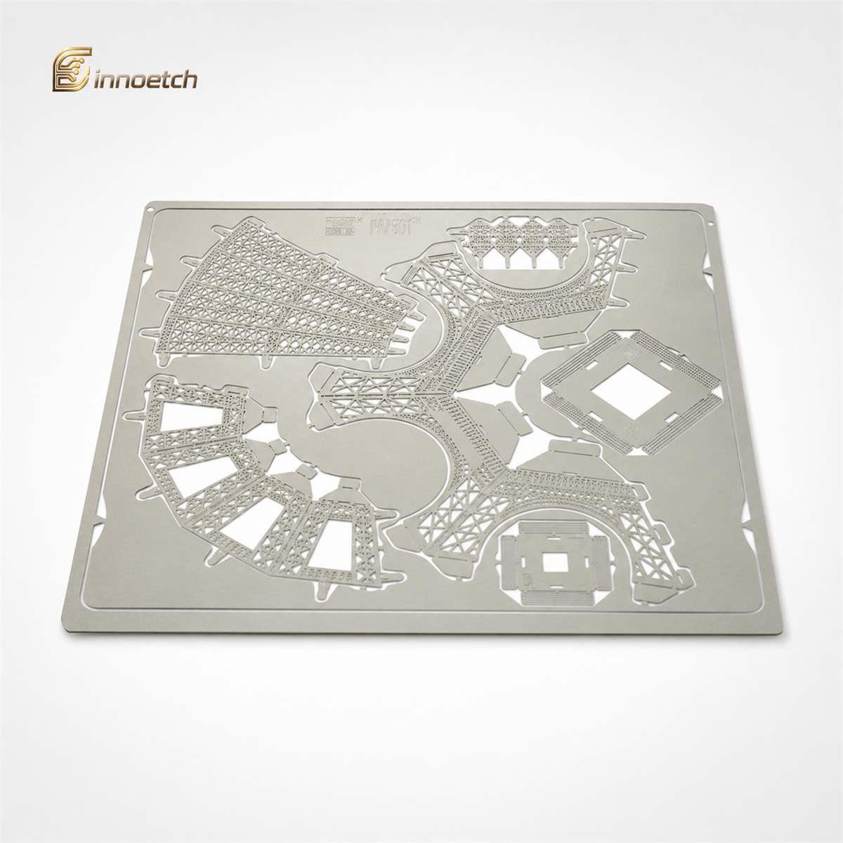
Shows how engineers can prepare CAD files for etching with clear dimensions, tolerances, materials, thickness, and feature notes.
Precision metal etching, also known as photo chemical etching or photochemical machining, is widely used to manufacture thin, complex, burr-free metal components. Engineers use it for precision shims, metal mesh, speaker grilles, filters, electronic components, shielding parts, springs, nameplates, and structural metal parts.
However, even the best etching process depends on clear engineering data. If the CAD drawing is incomplete, the manufacturer may need extra clarification, which can delay quotation, sampling, tooling, and mass production.
Below are the key CAD drawing requirements engineers should follow when preparing files for precision metal etching.
The most useful file formats for precision metal etching are clean 2D vector files and fully dimensioned engineering drawings.
Recommended formats include:
For most etched parts, a 2D CAD file is more important than a 3D model because the etching process is based on flat sheet metal geometry. A 3D model can still be helpful when the part includes forming, bending, assembly relationships, or functional fit requirements.
Yes. Engineers should always provide CAD drawings at full 1:1 scale.
A 1:1 drawing helps avoid scaling errors during tooling preparation. The file should use clear units such as millimeters or inches, and the drawing title block should match the units used in the CAD geometry.
Before submitting the file, check that hole sizes, slot widths, outside dimensions, and pitch spacing measure correctly in the native CAD file.
A complete precision etching drawing should include all information required to manufacture and inspect the part.
Essential drawing information includes:
Post-processing may include passivation, plating, polishing, deburring, cleaning, heat treatment, or forming.
Material selection directly affects etching quality, mechanical strength, conductivity, corrosion resistance, and cost. Engineers should avoid writing only “stainless steel” or “copper” if a specific grade is required.
A better format is:
INNOETCH works with custom etched metal components in materials such as stainless steel, copper, nickel, molybdenum, aluminum, and other advanced metals. The more specific the material callout is, the easier it is to evaluate feasibility, tolerance, and production cost.
Tolerances should be practical and function-based. Applying very tight tolerances to every dimension may increase cost without improving part performance.
Engineers should separate dimensions into:
For example, a connector contact area, spring feature, optical aperture, filter hole, or assembly slot may need tighter control than a decorative edge or non-contact outer profile.
A good drawing tells the manufacturer which features truly matter.
Holes, slots, and mesh patterns should be drawn as clean closed vector geometry. Avoid broken curves, overlapping lines, duplicated entities, and unclear imported artwork.
For dense hole patterns or precision metal mesh, engineers should clearly define:
If the pattern includes thousands of holes, it is helpful to provide one repeated unit with pitch information, plus a full pattern outline. This reduces file size while keeping the design clear.
Minimum feature size depends on material thickness, alloy type, tolerance, part geometry, and production volume.
As a practical starting point, small holes, slots, and bridge widths should usually be close to or larger than the material thickness. Very fine features are easier to etch in thinner metal.
Engineers should avoid designing extremely narrow webs unless they are necessary for the function. A feature that can be etched may still be too fragile for cleaning, packaging, assembly, or real-world use.
Half-etched features must be clearly identified on the drawing. Do not rely on color alone unless the color legend is clearly defined.
Common half-etched features include:
The drawing should specify whether the half-etch is on the front side, back side, or both sides. If depth is important, provide the required etch depth or remaining material thickness.
If the etched part will be bent or formed, the drawing should clearly show the flat pattern and the final formed shape.
Include:
Small holes and fine features should not be placed too close to bend lines unless the design has been reviewed for manufacturability.
Yes. If one surface is visible, decorative, conductive, plated, polished, or functionally important, it should be marked clearly.
This is especially important for:
Engineers should indicate whether scratches, discoloration, tool marks, or handling marks are acceptable.
A quotation-ready drawing should allow the manufacturer to understand the part without repeated back-and-forth questions.
To speed up quotation, include:
If the part is still in development, engineers can also provide design intent. This helps the etching manufacturer suggest practical design-for-manufacturing improvements.
Common mistakes include:
These issues can slow down engineering review and may cause production errors if not corrected early.
Engineers should contact a manufacturer early when the part includes fine holes, narrow slots, dense mesh, half-etched features, bending, tight tolerances, special materials, or high-volume production requirements.
Early communication helps confirm whether the CAD drawing is suitable for etching and whether the design can be optimized for cost, yield, and repeatable quality.
INNOETCH supports custom precision metal etching from prototype development to mass production, serving applications such as precision metal mesh, shims, elastic elements, semiconductor components, electronic parts, mechanical parts, structural parts, ornaments, and nameplates.
Engineers should prepare CAD drawings for precision metal etching with clear geometry, correct scale, complete material information, practical tolerances, defined critical features, and well-marked half-etched or formed areas.
A complete CAD package helps reduce quotation time, improve manufacturability, prevent production errors, and support stable batch production. For custom etched metal parts, the best results come from combining precise CAD data with early design-for-manufacturing review from an experienced metal etching manufacturer.
How Should Engineers Prepare CAD Drawings for Precision Metal Etching? is widely used in precision metal etching applications where clean edges, tight tolerances, complex patterns and stable performance are required. Typical industries include electronics, semiconductors, sensors, fuel cells, acoustic components, EMI shielding, thermal management and precision mechanical parts.
How Should Engineers Prepare CAD Drawings for Precision Metal Etching? is a precision metal component manufactured by photochemical etching for applications requiring accurate dimensions, smooth edges and reliable performance.
Common materials include stainless steel, copper, brass, nickel silver, titanium, aluminum and other thin metal sheets depending on the application requirements.
INNOETCH can process thin metal materials from approximately 0.02 mm to 1.5 mm, depending on material type, part structure and tolerance requirements.
For many precision etched parts, tolerances can reach ±0.01 mm to ±0.05 mm, depending on material thickness, design complexity and production volume.
Chemical etching does not require expensive hard tooling and can produce fine patterns, complex shapes and burr-free edges without mechanical deformation.
Yes. INNOETCH supports custom drawings, materials, thicknesses, hole patterns, surface finishes, dimensions and prototype-to-mass-production requirements.
2D drawings, DXF files, DWG files, STEP files, material requirements, thickness, tolerance, quantity and application details are recommended for accurate quotation.
You can send your drawings and technical requirements to INNOETCH. Our engineering team will review the design and provide a quotation.